


 Akzeptierte Antwort
1. Cutting Direction (Tool Rotation)
Among the tool parameters, there is a parameter that specifies the cutting direction (spindle rotation direction). For applications with less stringent requirements, it is advisable to use the same rotation direction wherever possible. This minimizes processing discrepancies between two identical curves that may arise from differences in tool rotation direction.
2. Eccentricity Compensation (Tool Runout Compensation)
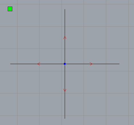
The tool parameters also include an eccentricity compensation setting. To determine whether eccentricity compensation is needed, a cross-shaped test pattern can be cut by moving the tool in four directions (X+, X–, Y+, Y–) to form a cross.
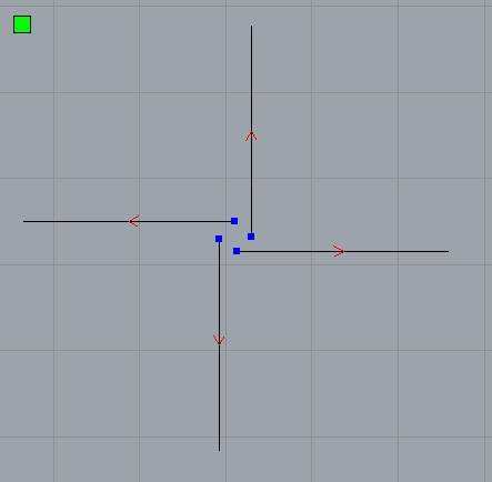
If Y‑direction eccentricity exists, the resulting cut pattern will appear as shown in the figure. By adjusting the eccentricity compensation value, the cutting path can be restored to normal.
Eccentricity is generally related to the mechanical precision of the tool holder/spindle. Where conditions permit, replacing the tool holder can be attempted for testing purposes. Setting eccentricity compensation can correct this error within a limited range; however, if the error is excessively large, it may adversely affect the actual machining quality.
3. Lead/Lag Compensation (Tip Advance/Retard Compensation)
Lead/lag compensation refers to the fact that the rotational center of the tool does not coincide with the cutting edge; instead, the cutting edge has a certain lead or lag relative to the rotational center. In the illustration, the black line represents the original curve, the red line shows the trajectory without lead/lag compensation, and the green line shows the trajectory with lead/lag compensation applied. With lead/lag compensation, the tool path can follow the original contour more closely, especially at corners.

Okay